| Previous | 14.1 Specifics of measurement server types | Next |
|---|
14.1.15 EthernetOAM measurement servers
The EthernetOAM measurement server implements some of the Ethernet Operation and Maintenance protocolls described in the IEEE P802.1ag/D8.1 and ITU-T Y.1731 standards. The collector server is only supported on the Linux platforms. The measurement server offers five features:
· Shadow device: the measurement server acts as a Layer2 shadow device and answers the incoming LBM and DMM messages and periodically sends the CCM measurements. These operations do not result measurement values
· CCM measurements: the server receives CCM messages and calculates availability measurements based on these messages.
· Round-trip-time and availability measurements: the module sends periodically Loopback messages and calculates availability and round-trip-time measurements from the response messages
· Loopback test: the user can also manually start a Loopback test. The test results are also saved and so the user can view them at any time
· Linktrace test: the user can also manually start a Linktrace test. The test results are also saved and so the user can view them at any time
The collector module is listening on the physical and/or logical interfaces for incoming packets and sends its own packets out on the same interfaces. The collector server does not handle VLANs itself. If two different VLANs send packets to one of the physical interface on the server then these VLANs must be configured on the machine as logical interfaces. This must be done by the root user manually.
A PVSR device can be assigned to such a physical or logical interface and two or more equipments must not be assigned to the same interface. The Timeout and Retry equipment parameters are ignored by the collector module. The EthernetOAM equipments have the following additional parameters:
· Ethernet interface: the interface assigned to the equipment, for example eth0. Mandatory parameter
· MD level: it sends the CCM messages with the MD level set here and it looks for those messages which have this MD level set. The possible values are (bold is the default):
o 0 - Operator
o 1 - Operator
o 2 - Operator
o 3 - Service Provider
o 4 - Service Provider
o 5 - Customer
o 6 - Customer
o 7 - Customer
· MD name format: the format of the MD name parameter used in the CCM messages. The possible values are (bold is the default):
o None: although the MD name parameter is not used in this case, it still must have a value
o Domain name based
o MAC address + 2-octet integer: in this case the MD name parameter must be formated as "XX:XX:XX:XX:XX:XX-n", where the six XX represents the MAC address elements as hexa strings and n is the number value. For example: 01:ab:CD:eF:45:aa-192
o Character string
· MD name: required string parameter
· MA name format: the format of the MA name parameter used in the CCM messages. The possible values are (bold is the default):
o Primary VID (number between 0 and 65535)
o Character string
o 2-octet integer
· MA name: required string parameter
· CCM interval: how often should it send the CCM messages and how often does it expect a CCM message from each device. The possible values are (bold is the default):
o 10 ms
o 100 ms
o 1 s
o 10 s
o 1 min
o 10 min
· PVSR MEP identifier: the MEP identifier used by the PVSR data collector shadow device when sending a CCM message. Required number parameter, default value is 1
· CCM multicast address: the MAC address used for sending the multicast CCM messages. The value can be a MAC address or the 01:80:C2:00:00:3y value (this is the default), where y will be automatically replaced according to the MD level and the IEEE standard
· Linktrace multicast address: the MAC address used for sending the linktrace messages. The value can be a MAC address or the 01:80:C2:00:00:3y value (this is the default), where y will be automatically replaced according to the MD level and the IEEE standard
PVSR does not validate the values during the equipment configuration, but the data collector does. Not just the assigned interface, but the MD level - MD name - MA name triplet also must be unique among the PVSR equipments.
There are MEP level and equipment level EthernetOAM measurements.
The MEP level measurements are the following. The Index parameter contains in each case the MEP ID
· Received valid CCM packets: how many valid CCM packets were received from a MEP in the last measurement cycle. A packet is only valid if its CCM interval is the same as the interval specified for the equipment
· Skipped CCM sequences: how many CCM sequences were skipped in the last measurement cycle. If the CCM sequences were 1, 3 and 6 then the value is 1 + 2 = 3
· CCM error state: it is either 0 or 1. It is only 1 if there was a CCM interval error timespan in the last measurement cycle (the CCM interval in the message was different from the CCM interval specified for the PVSR equipment and the 3.5x interval time have not expired yet) or there was a timeout timespan (no CCM was received from the MEP for 3.5x interval time)
· MEP RDI state: it is either 0 or 1. It is only 1 if CCM error state is 1 or if the interface status presented in the CCM packet is not isUp
· RTT: round-trip-time measurement calculated from the responses to the periodically sent Loopback messages, the unit is milliseconds
· Availability: availability measurement calculated from the responses to the periodically sent Loopback messages, the unit is percentage
The rtt and the availability measurements have additional parameters:
· Sample: how often should PVSR send a Loopback message. The unit is seconds. The parameter is mandatory and cannot be less than 1
· Timeout: after how many seconds should the message be timed out. The parameter isn't mandatory and cannot be less than 1 or greater than the value of the Sample parameter. If it isn't specified then its value will be the same as the value of the Sample parameter
· Size: the payload size in bytes. The parameter isn't mandatory and cannot be less than 10. If it isn't specified then its value will be 50
When a user opens an EthernetOAM equipment under the Measurement menu then he does not see the individual charts just yet. Instead PVSR shows so called measurement groups, each group representing one MEP, and only by clicking on the icon of a group will its charts be visible (i.e. there is an additional hierarchy level between the equipment and measurement level).
The equipment level measurements:
· Unknown MD/MA seen: it is either 0 or 1. It is only 1 if an unknown MD/MA value was received on the interface. The error condition lasts for 3.5 interval
· Unknown MEP identifier seen: it is either 0 or 1. It is only 1 if an unknown MEP identifier was received. The error condition lasts for 3.5 interval
· RDI state: it is either 0 or 1. It is 1 if either Uknown MD/MA is 1 or Unknown MEP is 1 or if one of the MEP RDI state measurement is 1 or for every MEP the received port status is not psUp
The PVSR shadow device sets the RDI flag in the outgoing CCM messages according to the RDI state.
The module has two test capabilities: Loopback and Linktrace. These tests must be started manually and they do not affect any measurement data. The results of the tests are also stored in the database and can be viewed at any time. The tests are available from the Operation drop-down list when the user views an EthernetOAM equipment or measurement in the Measurement menu. The parameters of the tests and their results are the following:
14.1.15.1 Loopback test
The application runs the Loopback test using the interface belonging to the choosen equipment (for example eth0.1). The application needs a destination MAC address, which can be specified in two ways:
· By choosing a MEP: the application will use the MAC address belonging to that MEP
· By specifying a MAC address. To do so the user has to select the last item from the drop-down list (--- MAC address ---) and then fill in the MAC address. The format of the address is XX:XX:XX:XX:XX:XX, where XX represents a two-digit hexadecimal number
The test has several other parameters too, and all of them are required:
· Sample: how often should PVSR send a Loopback message. The unit is seconds. The parameter cannot be less than 1 and its default value is 1
· Timeout: after how many seconds should the message be timed out. The parameter cannot be less than 1 or greater than the value of the Sample parameter. Its default value is 1
· Size: the payload size in bytes. The parameter cannot be less than 10 and its default value is 50
· Number of messages: number of messages sent during the test. The parameter cannot be less than 1 and its default value is 5
A successful test running requires that the data collector module belonging to the equipment is up and running and the server on which the module is running is accessable from the server running the WEB UI via SSH. Also the equipment must exist in the configuration of the data collector, so a couple of minutes must pass after the equipment creation before the test can be used. If the destination is a MEP and not a MAC address then the MEP must also exist in the configuration of the data collector prior to the test, so a couple of minutes must pass after the MEP creation before the test can be used. In this case the test will be unsuccessful unless the data collector received previously at least one CCM message from the choosen MEP.
After the test completition the MAC address used as destination is shown, along with the average availability, the minimum/average/maximum round-trip-time and the result of the individual Loopback messages.
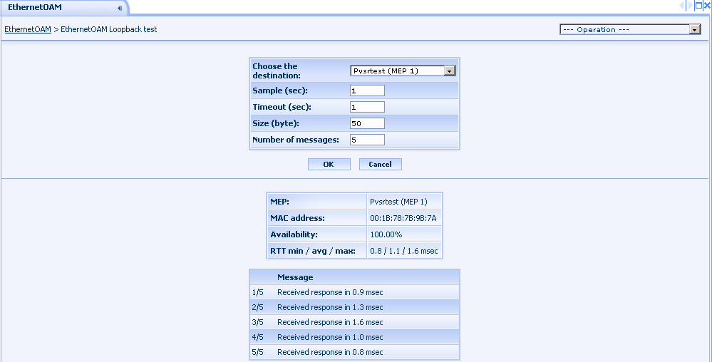
Figure 188. EthernetOAM Loopback test
The item "EthernetOAM Loopback history" in the Operation drop-down list can be used to access the result of the previous tests for the choosen equipment. The table only shows the major parameters, a more detailed view is accessible with the [view] link.

Figure 189. EthernetOAM Loopback history
14.1.15.2 Linktrace test
The application runs the Linktrace test using the interface belonging to the choosen equipment (for example eth0.1). The application needs a destination MAC address, which can be specified in two ways:
· By choosing a MEP: the application will use the MAC address belonging to that MEP
· By specifying a MAC address. To do so the user has to select the last item from the drop-down list (--- MAC address ---) and then fill in the MAC address. The format of the address is XX:XX:XX:XX:XX:XX, where XX represents a two-digit hexadecimal number
The test has several other parameters too, and all of them are required:
· Timeout: how many seconds should the application wait for Linktrace responses. The parameter cannot be less than 5 and its default value is 5
· Use only MAC addresses from the Bridge Filtering Database: If set, indicates that only MAC addresses learned in a Bridge’s Filtering Database, and not information saved in the MIP CCM Database, is to be used to determine the Egress Port
· Time To Live: the maximum number of hops to the destination, including the originator (i.e. the PVSR collector server). The parameter cannot be less than 2 and its default value is 63
A successful test running requires that the data collector module belonging to the equipment is up and running and the server on which the module is running is accessable from the server running the WEB UI via SSH. Also the equipment must exist in the configuration of the data collector, so a couple of minutes must pass after the equipment creation before the test can be used. If the destination is a MEP and not a MAC address then the MEP must also exist in the configuration of the data collector prior to the test, so a couple of minutes must pass after the MEP creation before the test can be used. In this case the test will be unsuccessful unless the data collector received previously at least one CCM message from the choosen MEP.
After the test completition the MAC address used as destination is shown. PVSR also shows whether the test was successful or not, i.e. the target MAC address has answered or not. It also shows the Linktrace response messages in a table. A row in the table is yellow if PVSR assumes that the device which has sent the message is not along the path to the destination MAC address or when it cannot determine whether the device is along the path or not.
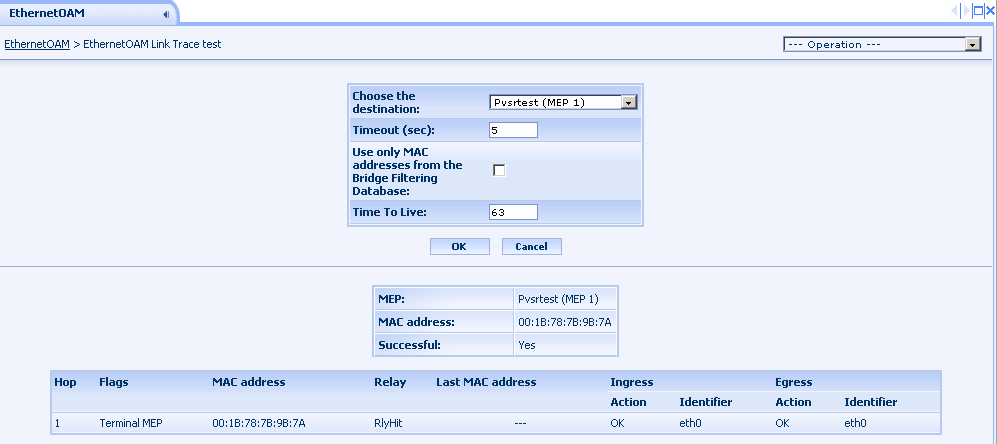
Figure 190. EthernetOAM Linktrace test
The item "EthernetOAM Linktrace history" in the Operation drop-down list can be used to access the result of the previous tests for the choosen equipment. The table only shows the major parameters, a more detailed view is accessible with the [view] link.

Figure 191. EthernetOAM Linktrace history